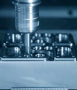
Basic Operating Steps Before the CNC Machining Center Starts
CNC machining center processing performance of a wide range of applications. In the use of CNC machining center, there are some details of knowledge the processing personnel need to master. The following is a detailed analysis of the steps required before the CNC machining center starts.
I. The preparation of CNC machining center before the start of operation
When CNC machining center (whether it is a horizontal machining center or vertical machining center) machine tool starts or stops, we should first make the machine reference into zero, so that the machine tool for future operations is in the position of the benchmark.
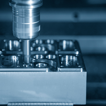
Ⅱ. Clamping workpiece of CNC machining center
Before the Workpiece clamping, we need to clean each surface that can not be stained with iron filings, dust and oil. And we need to use files or oil stone to remove the burr on the surface of the workpiece. The iron for clamping must be grinded by the grinder to smooth each surface, so that it is smooth and flat. Iron pads are generally placed at the four corners of the workpiece, and for parts with too large a span, a contour iron pad must be placed in the middle;
According to the dimensions of the drawing, we should use a ruler to check whether the length, width and height of the workpiece are qualified.
When Clamping workpiece, according to the programming work instructions for clamping placement, we need to open rate to avoid the tool head touching the fixture. When the workpiece is placed on the iron pad, according to the requirements of the drawing of the workpiece datum pull table, we need to test whether its verticality is qualifiedthe as to the workpiece that has been ground. After the completion of the workpiece pull table, we must tighten the nut to prevent the clamping from being not secure so that the workpiece, in the processing of displacement, will be misplaced. We need to pull the table again to determine the clamping error does not exceed the specified value.
Ⅲ. Collision number of CNC machining center workpiece
The clamped parts can use the collision head to set the reference zero position of the touch number, and the collision head can use the photoelectric and mechanical methods. There are two methods: the middle collision number and the single side collision number.
Ⅳ. CNC machining center's tool preparation
The programmer selects the parts to be processed, programs them through the CAM software UG, generates the tool path, carries out interference check through the UG simulation simulation module, and then carries out the processing after the interference check to generate the safe and stable NC code. Then they transmits it to the workshop and then to the machine.
Prepare all the tools according to the programming work instructions, change the tool to be machined, let the tool touch the height gauge placed on the datum, and set the relative coordinate value of this point to zero when the red light of the gauge is on. Move the tool to a safe place and manually move the tool downward by 50mm, then set the relative coordinate value of this point to zero, which is the zero position of the Z-axis.
Record the mechanical coordinate Z value of this point in one of G54~G59. This completes the zero setting of X, Y and Z axes of the workpiece. Once again, check the data carefully for correctness.
To check the correctness of the zero point, move the X and Y axes to the side overhang of the workpiece and visually check the correctness of its zero point according to the dimensions of the workpiece. Copy the program file to the computer according to the file path of the programming operation instruction.
V. Parameter setting of CNC machining center
Spindle speed setting in machining: N=1000×V/(3.14×D)
N: Spindle speed (rpm/min)
V: cutting speed(m/min)
D: Diameter of tool(mm)
Feed rate setting for machining: F=N×M×Fn
F: Feed speed(mm/min)
M: Number of tool edge
Fn: Cutting volume of the tool(mm/rev)
Cutting volume per edge setting: Fn=ZxFz
Z: Number of cutting edges of the tool
Fz: Cutting volume per edge of tool(mm/rev)

-
Common Faults and Classifications of CNC Machine Tools
Ⅰ. Classification according to the location of CNC machine tool failure1. Host failureThe host of a CNC machine tool usually refers to the machinery, lubrication, cooling, chip removal, hydraulic, pn... -
The 16th China International Machine Tool Exhibition (Cimt2019) Was Held In Beijing
On April 15, 2019, the 16th China International Machine Tool Exhibition (cimt2019), sponsored by China Machine Tool Industry Association and co sponsored by China International Exhibition Center Group... -
The Principle of CNC Turning Lathe Tool Setting
Ⅰ. The principle of CNC turning lathe tool settingI believe that everyone is already familiar with the "knife setting" in CNC turning lathe, but few people will "deeply study" the...
-
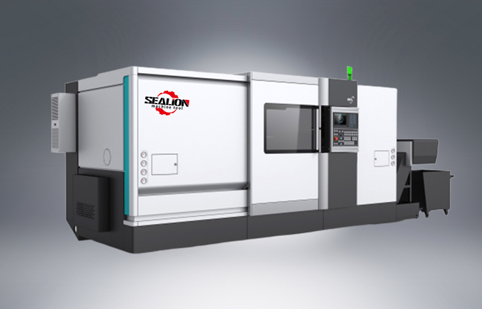
Lathe
-
CNC Boring Mill
-
CNC Machining Center
-
Fabrication Service
- Balls Screw Nut
- Components for Construction, Cgriculture and Cining Machinery
- Hydraulic Cylinders
- Hydraulic Pistons
- Machine Tool Components
- Valves
- Welded Components
- Bars & Tubes
- Bearing Rings
- Bearing Rolls
- Motor Shells
- Ceramic Parts
- Cylindrical Broaches
- Dreesing Tools
- Electric Motor Shafts
- Gearbox
- Gears
- Progressive Dies
- Pumps